Structural Analysis
Since
one spar cap is in tension and the other is in compression,
what you have is something like an earthquake fault line
between the spar
caps. They would like to move relative to each other in a sliding
fashion and
that is what shear webbing was invented to resist. The highest
load on shear
webbing is at the midpoint between the two spar caps. My patient Uncle
and I
examined the shear web loads on my 1/6 scale Cub spar design
and found that
1/64
ply was more than adequate for a spar 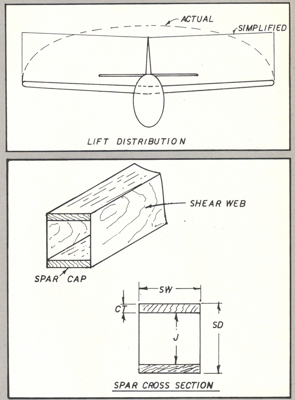 of those dimensions and
loadings (total
depth 1”, width 3/8”, spar cap thickness
1/8”). If your spar dimensions or
loadings go up by a factor of more than
two or three you might want to go to 1/32 ply for the
shear
webbing. Shear
loads are constant from
root to tip. If your spar at the wing
center section is solid top to bottom, along the center 10% of span
(approx.)
it will help resist shear loads.
of those dimensions and
loadings (total
depth 1”, width 3/8”, spar cap thickness
1/8”). If your spar dimensions or
loadings go up by a factor of more than
two or three you might want to go to 1/32 ply for the
shear
webbing. Shear
loads are constant from
root to tip. If your spar at the wing
center section is solid top to bottom, along the center 10% of span
(approx.)
it will help resist shear loads.
For the program to be valid the
spar must not be allowed
to buckle as you look at it in cross section from the wingtip. The wing ribs
do this job so they should not be too far apart. If the spar can buckle
it will
fail at a far lower loading. I usually don't go past 3 inches
on rib spacing unless the wing chord is more than 15 inches.
I
use this program to gain confidence in the strength of
my wing designs. It is a starting point, and should be followed up by
actual
failure tests of your wood and design,
especially if
you
are cutting close
to the margin on weight and load factor. Before
testing the sample
run the program a few times,
using a load factor of one and various
weights until you
arrive at a 100 percent rating in the design requirement
statement. Your sample
spar can be
about three feet long and should be supported in the middle. Load the sample evenly from tip
to tip until it fails. The weight the failure occurs at should be close
to the
100 percent rating weight predicted by the program. A variance
will most
likely be due to 9000 not being the
correct stress for your wood sample. You might want to lower this value if your samples consistently fail at too Iow a value,
or you
can look for some better samples of wood. Another thing that
will throw off the result is if your sample
is not exactly the size you are
putting into the program. Your measurements should be
within 1/64 of an inch, especially on
small sizes.
To
test for errors in the program after you type it, do a test
run using the values from the sample run which are for the 1/6 scale
Cub
spar. Remember, testing is central to the design process.
Calculations are only the starting point, and have to be compared to
the real
world by careful testing.
Page 4 of article ____ Golden Era Model
Service
Index
____
John Eaton Home Page