Golden
Era Model Service
High
Quality Plan Sets for Radio Control Aircraft
Carl Goldberg's 1938 Comet Clipper

The 3/16 foamboard base for outer wing panel construction.


The
extra outboard wing plan on sheet 3 has been cut out and taped to the
plan. It helps to cut the plan in a zig-zag pattern where it
mates to the base plan so there
are
more places to check the line up. The platform is then slid under
after the plan is taped together. You will be better off to
remove the inner wing panel from the plan to do this.
Leave
the spar fence attached to the spars, just unpin it from the plan.
It will be used to align the ends of the leading and trailing
edges.

A
straightedge is useful to get the platform in the correct position.
The straightedge needs a good sharp corner for accurate
placement. The corner should be right on the centerline
of
rib #11. Slide the platform in or out until the ruler lines up
and is just touching the plan at the centerline. When one edge is
correct pin it to the building board and do the other edge,
then go back and recheck both edges.

Rechecking the base alignment once the inner wing panel is back on the plan.

The
#17 rib is pinned to the plan at both ends to keep the parts in line.
The ribs are glued here, but that is only because the photo was
taken out of order. Mate the spars to the inner wing before
gluing any ribs.

The spars glued and clamped, and then all the ribs are aligned and glued.

The
spar fences have been removed and the second wing panel has been built.
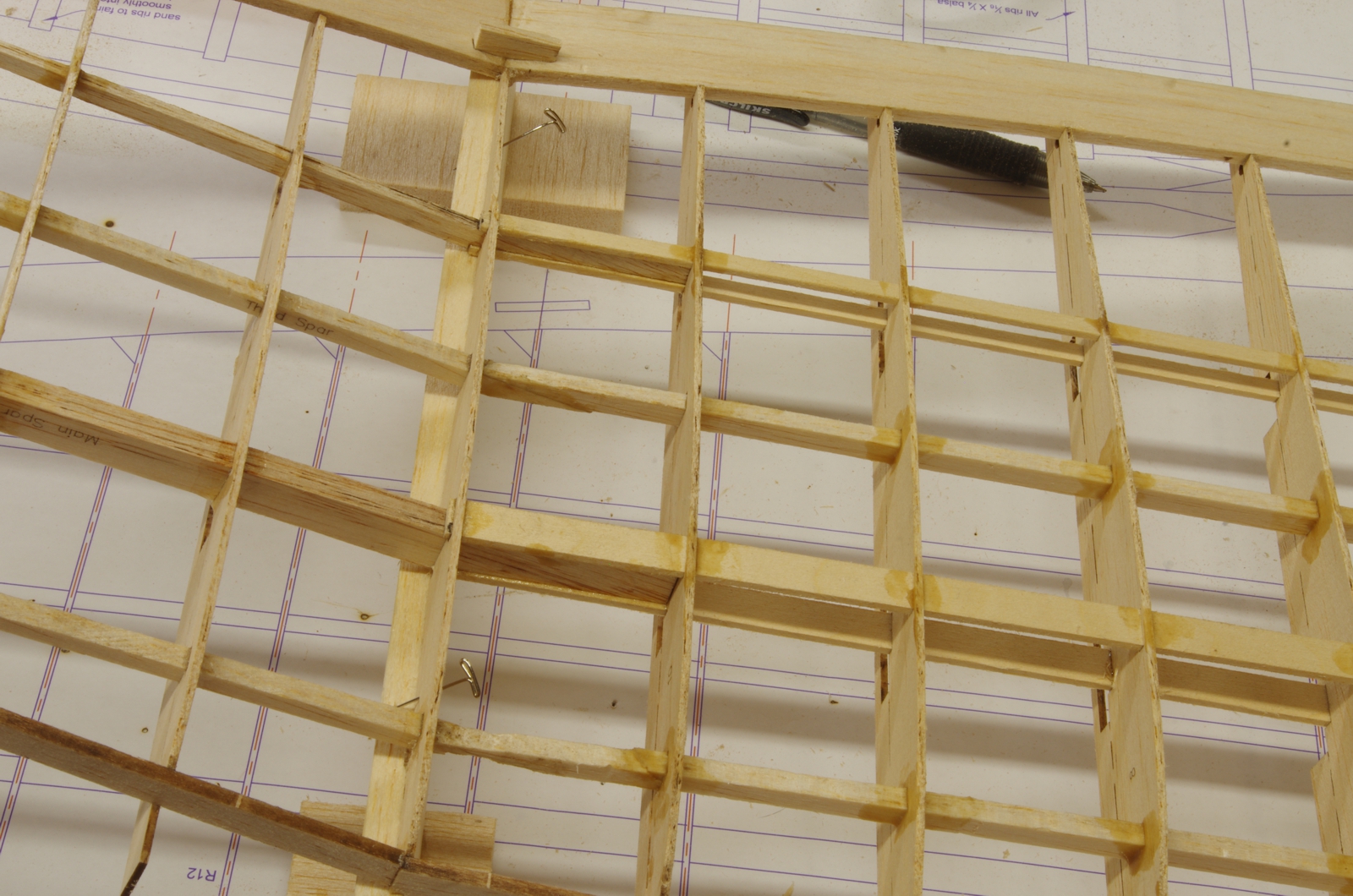
The upper spar center reinforcement sub-spars are shown here.
These
are blocks to hold rib #11 at the proper height when joining the
wing halves. Balsa was used so pins could be stuck in them.
These are 2 1/2 inches in height and were
used
with the feet removed from the #11 ribs. It may be more precise
to leave the feet on, if so the blocks should be 2.024" in height as
shown on the plan. Dimensions are
also shown for the blocking when the wing join is made with one wing panel flat on the plan.

A block under the left wing panel. The
block is pinned to the plan and the rib is pinned to the block.
The
block under the right wing panel. The rib is pinned to the block,
but the block is not pinned, but is free to move on the plan.
This is to allow fitting of the spars
at
the center join. Although the leading and trailing edge assembly
is started here, when the blocking is first installed on the right wing
panel these parts are absent. Photo taken out of order.

Installing
the upper spar doublers. Note that the leading edge parts on the
left wing panel are installed with the front sheet extending past the
centerline. Also note that the leading
and trailing edges are not yet installed on the right wing panel.
The right wing panel is bought up to the left and adjustments are
made to the spars so they all meet at the centerline. During this process check that the spars are aligned over the plans properly.
Clipper Mk
II Building Photos and Notes
Page 1 Page 2 Page 3 Page 4 Page 5 Page 6 Page 7 Page 8 Page 9 Page 10 Page 11 Page 12 Page 13 Page 14 Page 15 Page 16 Page 17 Page 18
GEMS
Index Page John Eaton's
Home Page
