Golden
Era Model Service
High
Quality Plan Sets for Radio Control Aircraft
74 inch San Josè
A 1948 design by Antonio Arria

As
I worked on the dihedral joint I realized it would be easy to put some
alignment marks on the plan so the complete wing assembly could
be set up over one of the wing panel front view drawings, so I did that
on Sheet 2. The alignment marks are to the right of the left wing
front view
with notes on how to line things up. The reference point is to
the last Rib 4 as it will be more precise than Rib 5 at the
polyhedral joint.
I did not make a two part wing so I made a gage from the extra
center rib to center the dihedral plate. I had a good idea on how
to set the upper
spar reinforcements when I built up the spars that turned out to be about exactly a half inch off. I should have just measured it to set them
instead.
Since the upper spar will never have high tension loads I just
filled the shortfall with spar material which will be fine for
compression
loads. My upper spar center point is a little loose but the
loads are all carried by the ply center plates there. If you have
this issue just
fill it with spar material, there is no strength in the butt join for
tension loads from inverted flight anyway. I have another idea I
may
try here
that I saw many years ago being used to repair broken baseball bats.
The fit on the lower spar is not critical as it will
have a splice installed later on. Within 1/16 of meeting will be fine.

Wing
panels all set up with triangles for the center wing join. I
inked in temporary marks on the plan sheet
used here, yours will be printed in conjunction with the left wing front views on plan sheet 2.

Center join with the 30 minute epoxy curing.

Here
is the tooling I made to try the baseball bat patch. The idea is
to put a curved plug in to a matching curve ground into the part to be
joined.
There is a plywood plate on the other side of the balsa circle
which was used as a sanding guide, and a section of laminated spar
material
was
glued on and sanded to shape. I was happy with how that worked
out. I made a companion circle, also backed with a ply plate
to
adapt it to an air die grinder. Sandpaper was glued on that, as
you see. Then I snatched defeat from the jaws of victory
because I could not hold the sanding wheel steady enough to get a good clean matching circle on the upper spar, it wanted
to move horizontally. However, it did leave me with nice smooth curves on the spars.

I
made some thin veneer-like sections of spar material and clamped them
against the spars. The area will be machined to the appropriate
shape.
Next
time I will use material that is a bit wider from front to back so
positioning in line with the existing spar is less fussy. This
method of
joining spars is one I have had in mind to use on the center section of
a gull wing glider I want to do. An obvious use for carbon fiber,
but
unless
many pieces are going to be made such a structure is difficult and
expensive because of the tooling involved. Thus the laminated
wood structure, not as efficient weight wise, but much easier for the home workshop to work with. The laminated beam has proven
to be practical in commercial building structures. Put a plug of spruce in the gap of your upper spar (if indeed you have one) and be done with it
unless you have fun with ideas like this as I do.

The upper spar laminations have been machined to contour and the lower spar splice has been installed but not yet profiled.

The sheeting support stringer has a pretty good bend at the last rib, so slit the stringer in the middle for
the last three inches to make it easier to form. Once in place a little thin CA can be flowed in the crack.

The
center section with the center rib in and basswood 3/16 square
rubber band supports installed. The supports were cut full
width and a saw cut was made in the center, allowing a crack there to ease the bend. The trailing edge join has been reinforced
with
lightweight glass cloth applied with thin CA. When installing the
forward part of the center rib, as well as the ribs at the polyhedral
breaks,
widen
the slot for the sheet support stringer so you can turn the rib in
place. This is necessary because of the birdbeak fit to the leading edge.

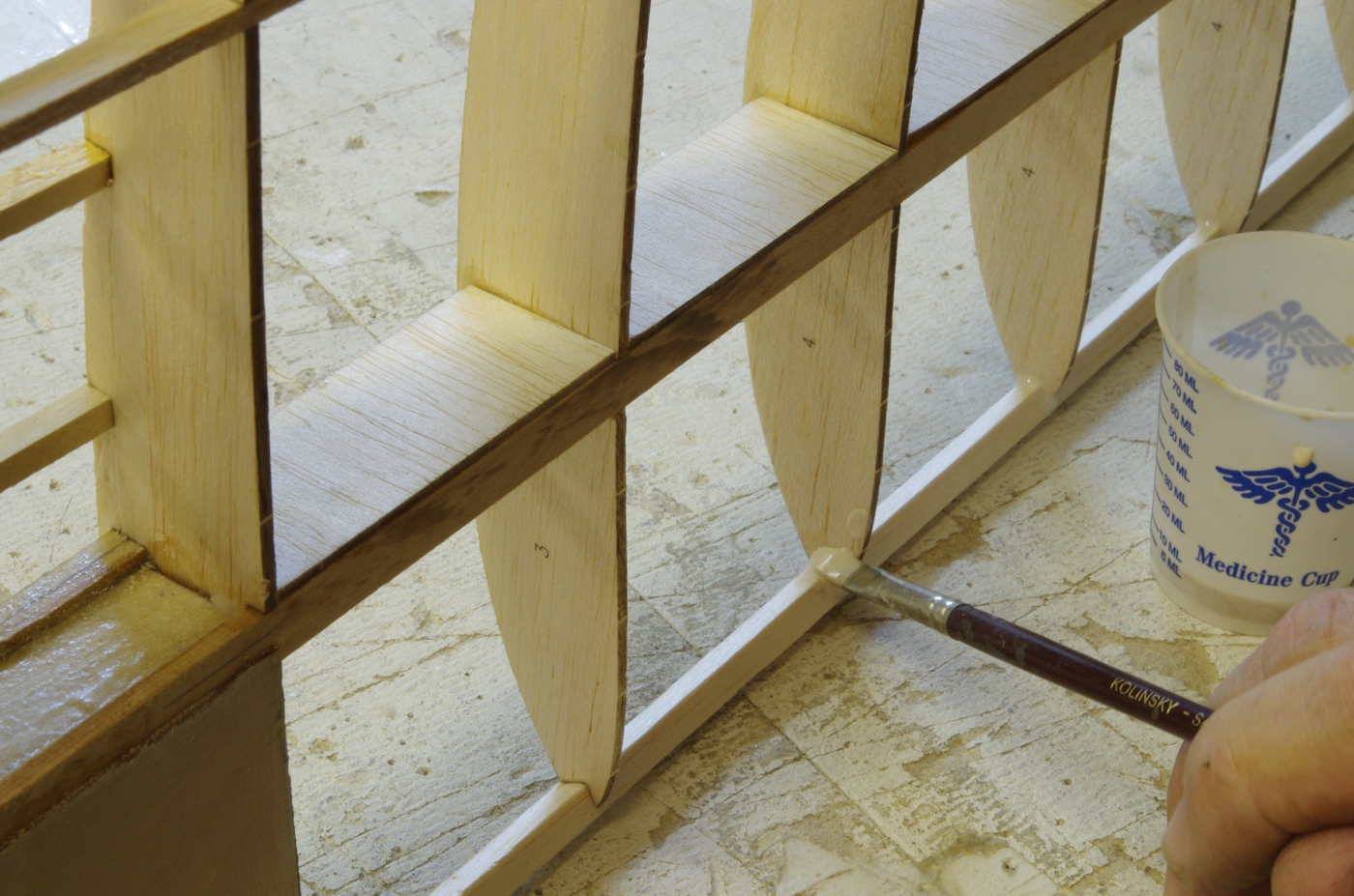
Next is the application of Titebond to all the glue joints in the wing, then the leading edge sheeting will be installed.
Previous San Josè page GEMS
Index Page John Eaton's
Home Page
San Jose First Page Next San Josè page