
Golden
Era Model Service
High
Quality Plan Sets for Radio Control Aircraft
74 inch San Josè
A 1948 design by Antonio Arria
Test fitting the bulkheads on the aluminum jig. The bulkheads fit snugly but not so tight as to hinder removing the jig.
A
front jig fixture was made up from scrap 1/4 inch plywood. The
supplied square hole plate is on the other side. Since I didn't
want to
take
photos of an crooked jig I took some pains to get it level fore and aft
and laterally. There is plenty of room at the tail for a 1/2 inch
square length
of maple to run across on the rear support. A clamp was placed
inside the front support to prevent the aluminum extrusion from moving.
A triangle is restraining the bar on the other end.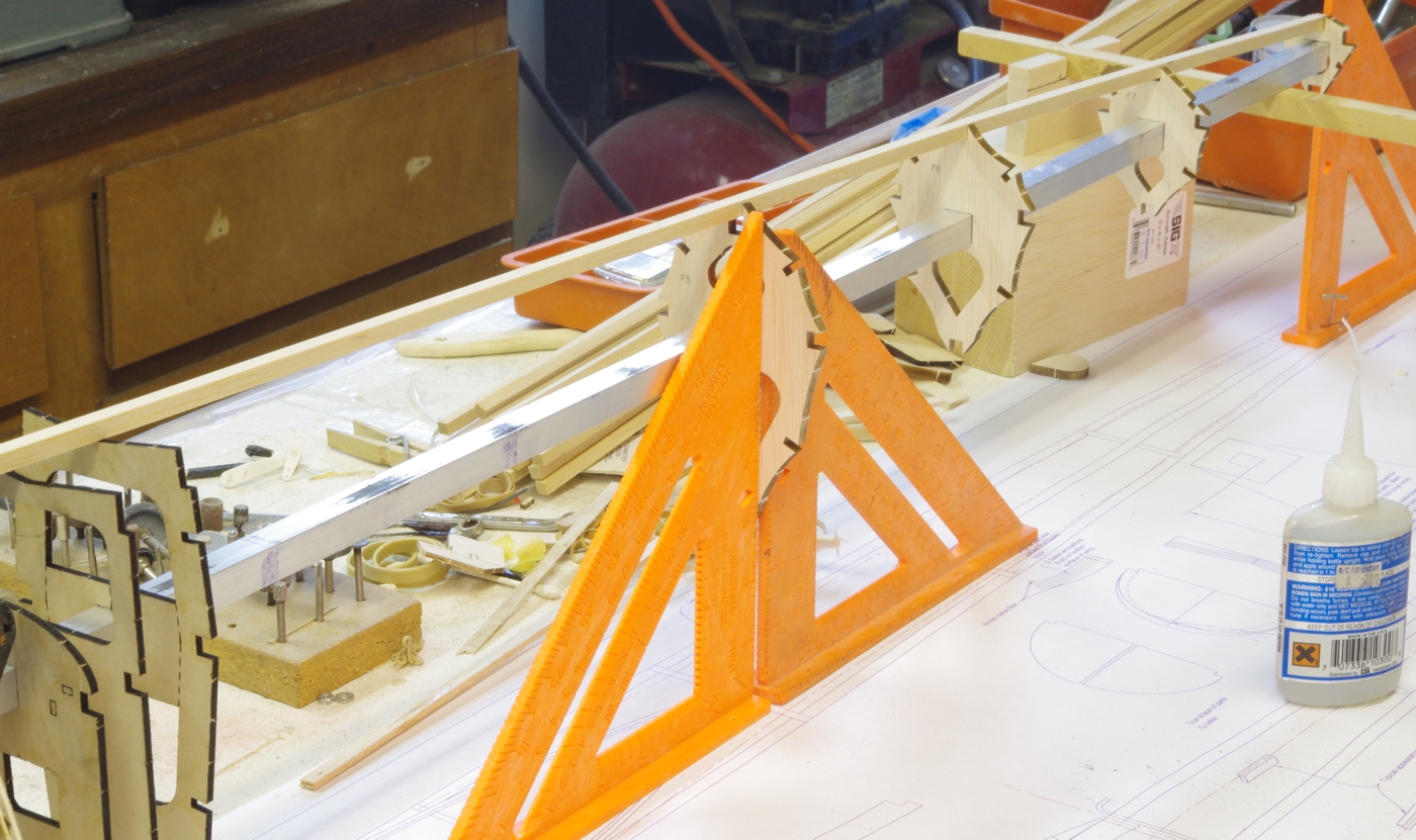
The jig is above the fuselage top view, and the triangles locate the F5 bulkhead as the top longeron is tacked in.
Remember to locate the top longeron at F5 so there is room for the tab on the top fuselage framing to fit beneath it.
From F5 aft the bulkheads can be done in any order, but the front ones are best done from F1 aft so there is room
for the triangles or whatever type of square you use.
I
did the top and bottom longerons at the same time, then left and right.
The side longerons will have to be spliced unless you have
48
inch stock, they measure a little under 43 3/4. Lastly the
quartering stringers of 1/8 x 1/4 are installed. It is better to
use flexible
stock as there is a twist from F3 to F5. There is a "wasp waist"
on the top stringers at F5 that will want to draw out the stringer
between F6 and F7 slightly in reaction. A little sanding between F6 and F7 will correct that if desired.
A friend gave me the idea of using aluminum angle extrusions covered by plastic wrap to keep structures straight as they are
glued.
It is especially helpful on built up spars but works well for
simple jobs like joining longerons with scarf joints. I get
the angles the same by putting the companion sticks under a 3/4 square
length of hardwood and applying the end to the belt sander.
(Probably a process everyone else came up with before me.)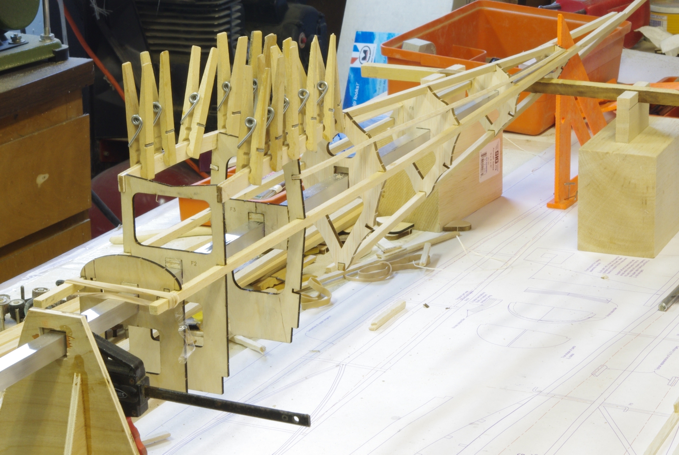
The upper cabin framing has been laminated and is curing in place. I used Titebond for this. The inside faces
of the aft ends of the framing need to be tapered to fit in the notch in F5 below the top stringer.
Installing the fuselage keels. The notches for the landing gear go just in front of the bulkheads so the wires
will rest against them. The aft end is 1/8 inch above the lower longeron to allow the lower fuselage plate to
fair at that point. The landing gear must be installed before the bottom plate.
Previous San Josè page GEMS
Index Page John Eaton's
Home Page
San Jose First Page Next San Josè page