
Golden
Era Model Service
High
Quality Plan Sets for Radio Control Aircraft
74 inch San Josè
A 1948 design by Antonio Arria
The
landing gear was attached with .041 safety wire. I drilled two
holes per side but it seemed solid enough with one wrap. Ply
gussets will
follow.
This is the simplified landing gear rather than the one that
Antonio Arria used. It gives more ground clearance for larger
props.
The
landing gear installed. The bending tool in the background was
used to make the initial bends after marking the bend locations with
tape.
I think it is made by Great Planes but could be wrong. Many final adjustments were made with a bench vise. The landing gear fits in the notches
in the keels and that helps the fitting process. The parts were taped to the bulkheads and to each other during the fitting process. The wire parts
were washed in a strong solution of dish soap and sanded to a shine
before soldering. The joints were wrapped with brass wire and
soldered
with
2% silver bearing solder. Normal electrical or plumbing solder is
not strong enough for landing gear construction. A propane torch
provided the heat.
Indentations were ground in the bottom plate so it was sure to clear the safety wire wraps.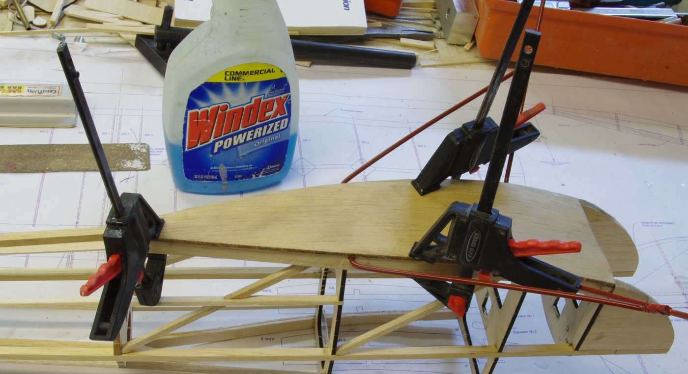
The
front edge of the bottom plate was glued to F1 and the first 1/2 inch
of the keel pieces. When that had cured the bottom was
soaked with Windex.
Here it
is clamped down to dry. A small amount was filed off of the tail
of the bottom part to fit snugly against the lower aft 1/4 square
longeron. Be sure
you
have the part aligned well with that aft lower longeron when you glue
it to the firewall. If the keels are not in perfect alignment aft
of the landing
gear you will be able to pull them out to conform to the bottom when you glue them after the Windex has dried.
Fitting the fin and stabilizer. First the 1/32 ply doubler was inset on one side.
With the fin spar next to the lower longeron marks were made in the cut location.
With
the relief for the second ply plate already cut, marks are again made
on the side of the lower longeron. The fin was removed and the
cut was made in the
lower longeron, followed by installation of the second 1/32 ply plate.
The reliefs on both sides need to be equal or the alignment of
the fin could be
upset.
Once the glue is well cured on the doublers test fit the fin to
make sure there is clearance. File the doublers and fin as
neccessary, checking
the vertical alignment of the fin and the centering of the stabilizer.
Once all that looks good install the subfin and then the 1/64
plates on both
sides of the subfin if you are doing the removable tail option.
Previous San Josè page GEMS
Index Page John Eaton's
Home Page
San Josè First Page Next San Josè page